Lab
Ship Grid Emulator
A. General Architecture In the framework of the MARINELIVE project, a ship electric power system emulator has been developed at the School of Naval Architecture and Marine Engineering of NTUA. The design of this prototype ship grid emulator has been performed by the NTUA team along with “Protasis s.a” which commissioned the complete final system. The system is actually an AC three-phase one, comprising Generation, Distribution, Consumption, Protection and Supervising Monitoring-Control sub-systems. A simplified one-line diagram of the system is shown in Fig. 1, in which dashed lines indicate installations not already existing but planned for the near future.
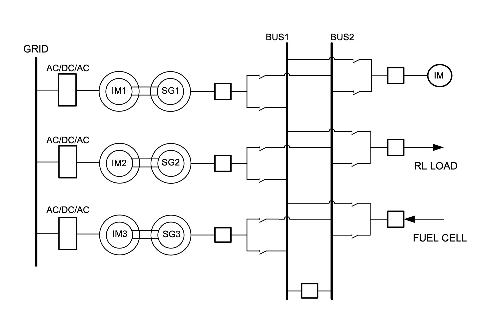
Fig. 1. One-line diagram of grid emulator
The power generation sub-system comprises three synchronous generators (two of 5.9 kVA/400V/50Hz/pf=0.8 ind. and one of 5 kVA/400V/50Hz/pf=0.8 inductive). The installation of some other power sources via a DC/AC inverter (e.g. a fuel cell) is foreseen to be integrated in the future, esp. considering that a fuel cell unit has also been purchased (NEXA K00-792 complete model with incorporated DC load and monitoring system. Note that as the generators are of low power, they produce Low Voltage (400 V), so no transformers are used in the system.
An induction motor fed by the local grid via an AC/DC/AC converter plays the role of the prime mover for each generator, while the fuel injection rule is emulated via the power electronic inverter rotating the prime mover - electric motor. On the other hand, the generator output voltage is regulated via installed Automatic Voltage Regulators (AVR’s) of BASLER. It is noted that the system is essentially electrically isolated with respect to the local grid, with the exception of auxiliary circuits (e.g. the AVR’s of the synchronous generators and protection relays).
The system loads are a passive RL load and a three-phase induction motor, see Figure 2). Similarly to the synchronous generators (but with opposite power flow), the mechanical load of the motor is another induction motor connected to an AC/DC/AC converter and acting as a regenerative brake. The ensemble of the motor and AC/DC/AC converter can be used to simulate various mechanical loads, e.g. a propeller.
To create contingencies to the system, a power circuit breaker has been installed to emulate three-phase faults, as well as a Power Quality event generator. The Power Quality event generator (sag Gen in Fig. 2) has been purchased from Power Standards Laboratory - PSL (USA). It is a complete unit IPC- 480V/200A, which is connected in series to the grid and can be programmed/controlled via a PC-based software so that well pre-defined power quality events (e.g. voltage sags of prescribed duration and amplitude) are provoked to the network.
The installation of an AC/DC/AC converter, which will be optionally used to feed the induction motor load of the system, is foreseen in the near future. In this way, it will also be possible to emulate motor loadings e.g. the electric propulsion by uploading the propeller dynamics (look-up tables of torque vs time) to the regenerative brake controller.
The power generation sub-system of the Grid emulator can be synchronized with the mains emulating the ship-to-shore connections following the “Cold Ironing” investigation studies.
The main features of the Grid Emulator are summarized in Table 1.
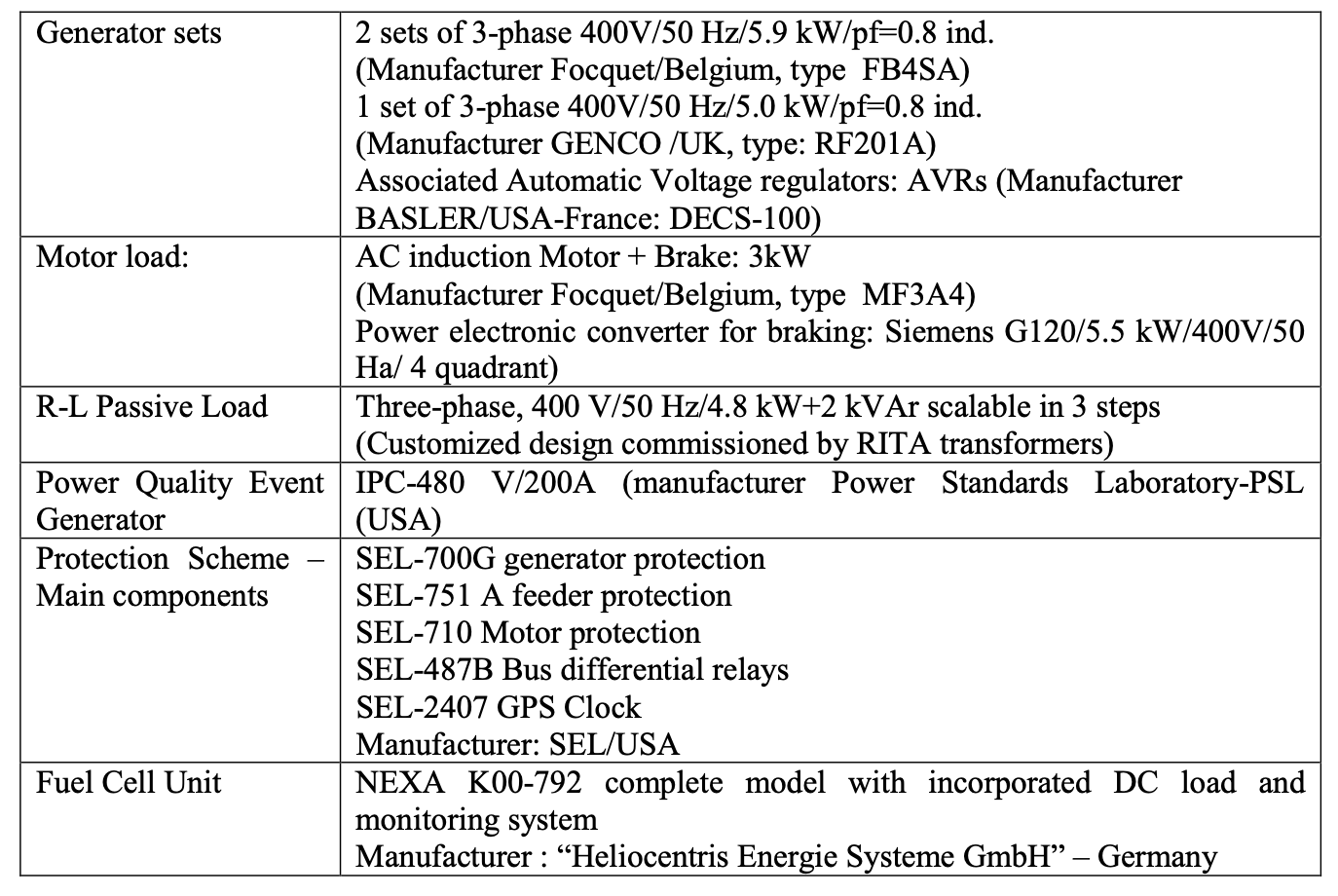
Table 1. Summary if Ship Grid Emulator equipment
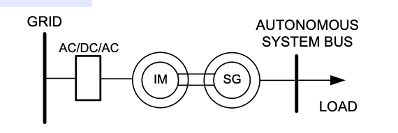
Fig 2
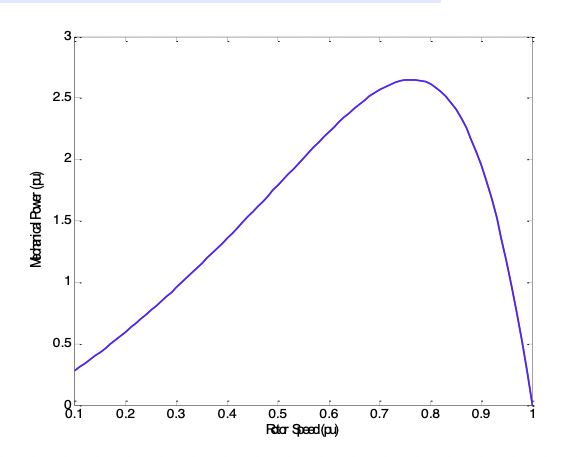
Fig 3
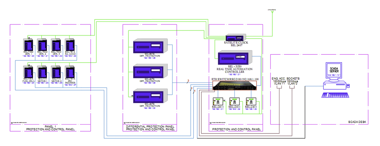
Fig 4. Data network architecture.
As shown in Fig. 1, all the relays and other devices are connected radially to the ETHSW via an Ethernet network (100Mbps - UTP Cat6). The data network functions are:
- Tele-metering and remote control data collection, IEC-61850.MMS protocol
- Exchange of data between the relays and between the relays and RTAC, IEC61850.Goose protocol
- Data for relay configuration event recording, TELNET & FTP protocol.
By means of the Human-Machine Interface (HMI) of the SCADA system (realized with specialized commercial software), various capabilities are provided:
- Close/Trip circuit breakers
- Close/Trip disconnectors
- Automated commands
- Increase/Decrease Step on Inverters (e.g. frequency control, active power sharing)
The information shown on the one-line diagram concerns the state of the circuit breakers and disconnectors, as well as electric measurements. This information comes from the digital protection and control devices. Available measurements of the HMI are:
- V oltages/Currents
- Active/Reactive Power (in or out a grid component)
- Cosφ (Power Factor)
- Energy
- Event/Alarm list
All measurements are stored every minute in the internal database of the HMI and can be extracted as Comma Separated Values (CSV) files or to an SQL database for further processing by other software.
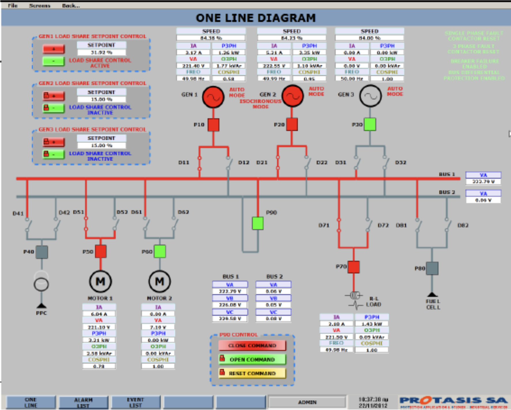
Fig 4a. Snapshot from the EPMACS of the Ship Grid emulator (two generators in parallel serving one motor and a passive RL load)
The DC extension planned is shown in Fig. 5. Figure 5a shows the rectifier which will be fed from the AC system. It is planned to be tailor-made at NTUA with simple diode-based bridges and capacitors. Figure 5b shows the DC bus fed by the rectifier, together with three DC circuit breakers and a PLC which will serve as a SCADA interface unit for their control and monitoring. Special devices for measuring DC current and voltage are also planned to be installed. Concerning the DC system load, one option will be the available motor of the AC system (motor IM4 in Fig. 1) by directly feeding the DC side of the AC/DC/AC converter of the motor load of the AC system. The design of the DC system is for a rated capacity of about 13 kW.
